A Guide to Bridge Rectifier Circuit Circuit Diagram
BlogA Guide to Bridge Rectifier Circuit Circuit Diagram Learn how to use four diodes to convert AC to DC with a diode bridge rectifier circuit. See the diagram, how it works, and what it's used for in power supplies and other circuits.
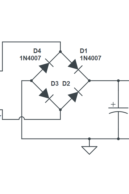
Learn how to convert AC to DC using a bridge rectifier, a type of full-wave rectifier with four diodes in a bridge circuit. See the diagram, waveforms, characteristics, efficiency, advantages and disadvantages of bridge rectifier. Learn how to convert AC voltage into DC voltage using four diodes in a bridge configuration. See the circuit diagram, waveforms, formula, advantages, and disadvantages of full wave bridge rectifier.
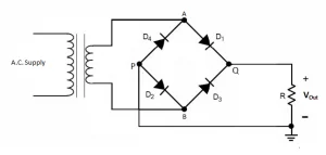
Full Wave Rectifier Circuit Diagram
Learn how to convert AC to DC using a bridge rectifier, a circuit made of four diodes arranged in a bridge configuration. See the circuit diagram, waveform, and operation of a bridge rectifier and its applications in various electronic systems.
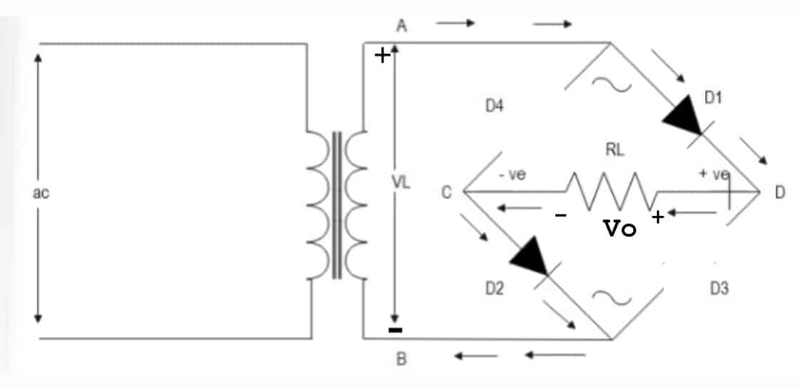
Learn how to convert AC to DC using a bridge rectifier circuit with four diodes and a transformer. Find out the advantages, disadvantages, and types of bridge rectifiers and their applications in electronic power supplies. Learn how to convert AC voltage into pulsating DC voltage using four diodes in a bridge configuration. See the full wave rectifier circuit diagram, output waveform, and how to add smoothing capacitors. Learn how to convert both half cycles of AC to DC using a bridge rectifier with 4 diodes. See the circuit diagram, input and output waveforms, and analysis of peak current, output current, DC voltage, and ripple factor.

Full Wave Rectifier and Bridge Rectifier Theory Circuit Diagram
Learn how a bridge rectifier converts AC into DC using four diodes and a load resistor. See the diagram, the working principle, and the characteristics of this full wave rectifier circuit.
